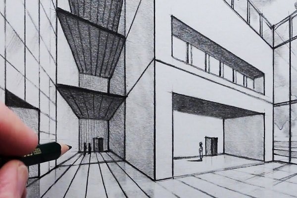
Building Structure Drawing
Building Structure Drawing
Building structure drawings are technical representations that outline the structural components of a building. These drawings are essential for ensuring the building's stability, strength, and safety during and after construction. They are prepared by structural engineers and are critical for architects, contractors, and builders.

Types of Building Structure Drawings
Foundation Plan:
- Depicts the layout and dimensions of the building’s foundation.
- Includes footings, piles, piers, and slab details.
- Highlights load-bearing walls and columns.
Framing Plan:
- Shows the arrangement of beams, joists, and trusses.
- Used for designing floors, roofs, and walls.
- Includes details like spacing and material specifications.
Structural Elevations:
- Vertical representations of the building’s structural components.
- Displays the heights and relationships between different levels.
Column Layout:
- Provides the location and dimensions of columns.
- Indicates column types, reinforcement details, and load specifications.
Reinforcement Detailing (Rebar Drawings):
- Shows the placement and specifications of reinforcement bars (rebar) in concrete structures.
- Includes details for beams, slabs, columns, and footings.
Beam Layout:
- Details the size, spacing, and connections of beams.
- Indicates load-bearing capacities and materials.
Roof Structure Plan:
- Depicts the design of the roof, including trusses, rafters, and purlins.
- Includes drainage points and materials.
Staircase Detailing:
- Provides the layout, dimensions, and reinforcement of staircases.
- Includes step height, width, and handrail details.
Shear Wall Layout:
- Shows the placement of walls designed to resist lateral forces (e.g., wind or earthquake).
Section Drawings:
- Cross-sectional views of the structure, showing internal details of components.
- Useful for understanding layering and connections.
Components of Structural Drawings
Structural Symbols and Notations:
- Represent elements like beams, columns, and reinforcements.
- Standardized by organizations like ISO or AISC.
Material Specifications:
- Defines the materials used (e.g., concrete grade, steel type).
Load Details:
- Includes dead loads, live loads, and environmental loads (e.g., wind, seismic).
Scale and Dimensions:
- Provides accurate measurements and proportions.
Sections and Details:
- Enlarged views of complex connections or critical areas.
Notes and Annotations:
- Include construction instructions, tolerances, and safety considerations.
Standards and Codes for Structural Drawings
- American Concrete Institute (ACI): Guidelines for concrete structures.
- American Institute of Steel Construction (AISC): Standards for steel structures.
- Eurocodes: Structural design codes used in Europe.
- International Building Code (IBC): Comprehensive code for structural safety.
Working With The Best
Our Partners


